Pages

Showing posts with label hangar. Show all posts

Vertiport Design for Fire Protection Professionals [a Review of the FAA Engineering Brief]


A few weeks ago the FAA released a draft version of its
Vertiport Design Engineering Brief. I have compiled the most important information that would be applicable to fire protection professionals who may be reviewing these plans, working through a concept of operations, or ultimately required to respond to emergencies.

This document has been created to provide facility design guidance  for VTOL aircraft powered by “electric motors and utilizing distributed electric propulsion in contrast to propulsion systems built solely around an internal combustion engine.” This guidance applies to modification of existing facilities and construction of new facilities. This guide is required to be followed by any vertiport projects that receive federal funding and by federally obligated airports. These facilities will also be required to comply with 14 CFR Part 135, Operating Requirements: Commuter and On Demand Operations and Rules Governing Persons On Board Such Aircraft.

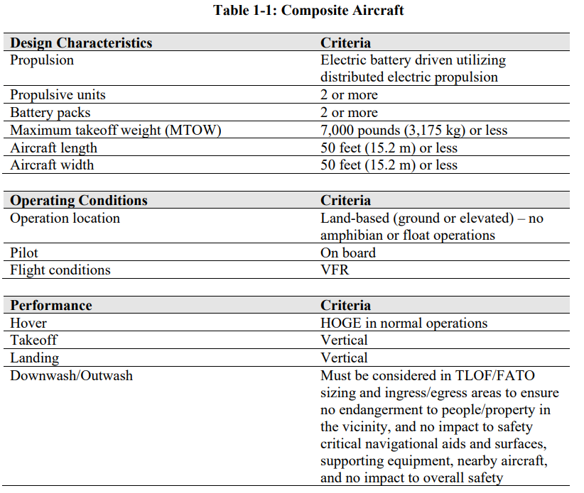
This design guide is based on pilot-on-board, visual flight rule operations, and aircraft characteristics as modeled in the below chart. The chart below was created from a composite of nine different eVTOL aircraft currently being developed. 


Terminology and Definitions


  • Composite Aircraft: the composite aircraft represents an VTOL aircraft that integrates the performance and design characteristics of nine VTOL aircraft currently in development. This composite aircraft is used to specify the performance and design characteristics for the purposes of vertiport design in this engineering brief.

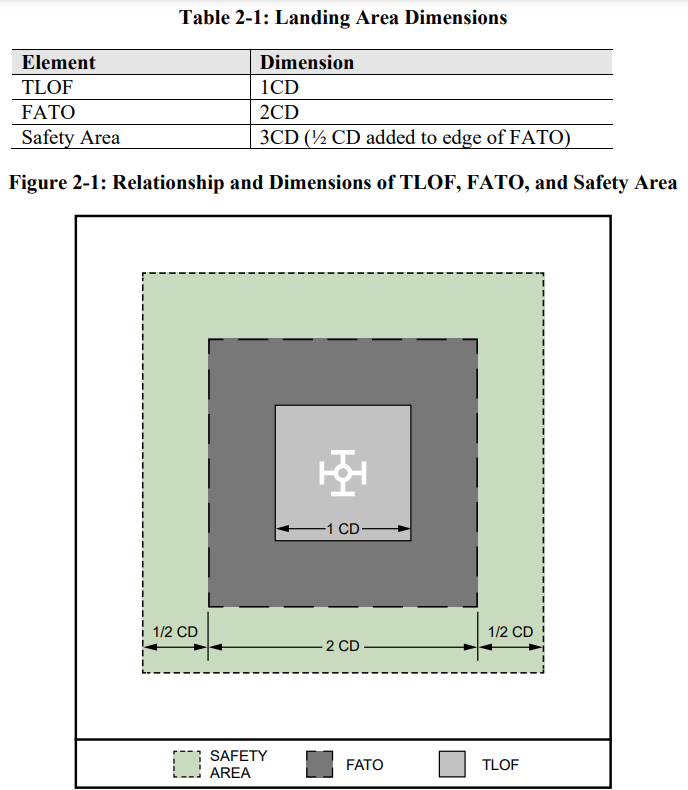
  • Controlling dimension (CD): The CD is the longest distance between the two outermost opposite points on the design VTOL aircraft (e.g., wingtip-to-wingtip, rotor tip-to-rotor tip, rotor tip-to-wing tip, fuselage-to-rotor tip), measured on a level horizontal plane that includes all adjustable components extended to their maximum outboard deflection.

  • Design VTOL aircraft: The design VTOL aircraft is the largest electric, hydrogen, or hybrid VTOL aircraft that is expected to operate at a vertiport. This design aircraft is used to determine the size of the TLOF, FATO and safety area. Note that the design VTOL aircraft is different from the composite aircraft used to define the performance and design criteria in this engineering brief.


Vertiport Dimensions and Markings


Any vertiport that is being built on a federally obligated airport must submit an Airport Laoyout Plan (ALP). Current heliport facilities that are being converted to vertiports will be required to submit a Form 7480-1 for re-designation as a vertiport.  Additionally, any State of local regulations must be followed. These can be found at, https://www.faa.gov/airports/resources/state_aviation/.


The VTOL landing area is required to be based on the controlling dimension (CD) of the design aircraft that will be using the facility. Those design criteria are depicted below:


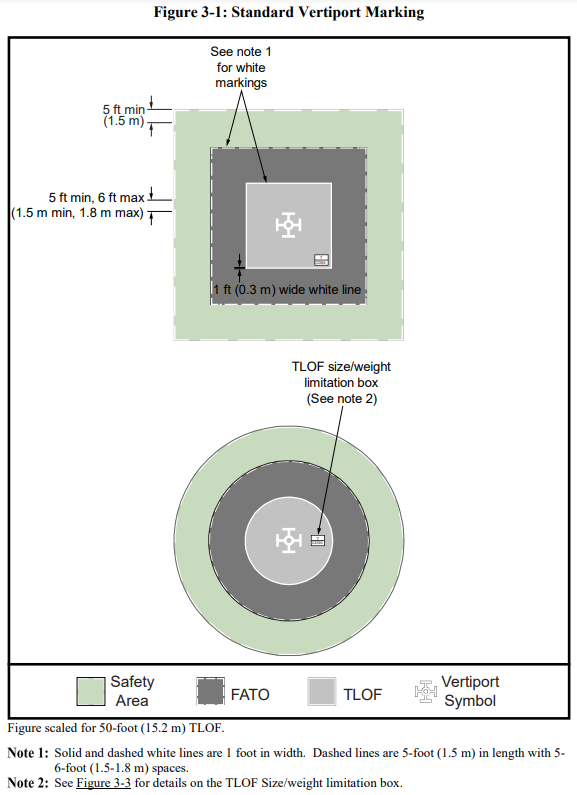
The vertiport landing and safety areas are required to be marked as shown in the diagram below:


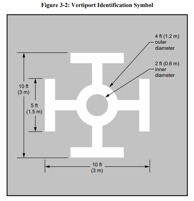
This brief also establishes and defines the an official vertiport identification marking:


Charging and Infrastructure


This engineering brief acknowledges the hazards and challenges of eVTOL charging and infrastructure. “Current charging standards for light duty vehicle charging (up to 350kw) align with multiple light electric aircraft currently applying for certification. However, higher capacity batteries and novel systems for meeting operation characteristics may require alternative chagrin methods including mobile charging systems, fixed battery storage, cable and/or on-board battery cooling, or other concepts.”  The guide then refers the user to a collection of standards that should be reviewed and applied. 


Firefighting Considerations


A brief section on firefighting acknowledges that there is no clear guidance on extinguishing fires related to these VTOL aircraft. A study is cited that states water is more effective for cooling, preventing thermal runaway, and containing the fire than was gaseous or dry powder agents. New technology on the horizon may prove to be even more effective than what is currently available. The hazards that responders should be prepared for and have an understanding of, include:

  • Lithium battery fires

  • Electrical fires

  • Toxic gas emissions

  • High voltage electrical arcing


Important Dates


The Engineering Brief and all related information can be accessed at the website here, https://www.faa.gov/airports/engineering/engineering_briefs/drafts/.


The Story of American Aviation


Aviation found me. It found me nearly fifteen years ago, sitting in class at the fire academy. Out of nearly 400 hours of training to become a firefighter in the state of Florida, aircraft rescue and firefighting (ARFF) is covered for about fifteen minutes. But, it was in these few minutes that I knew I wanted to work in the aviation industry, and ARFF specialty field.  My first fire department job out of the academy was indeed an aircraft rescue and firefighting job, a career I continue to enjoy to this day. 


I am proud to be part of the innovative and storied history, and continuing advancements, of the aviation industry. In 1946, Jim Ray, captured this history in his well written and beautifully illustrated book, The Story of American Aviation. Seventy-four years later, it is my privilege to be part of the team that has brought this book back into print. I consider it an honor to have written the foreword to this new edition.


Click to order.

Jim Ray described that his purpose for this book was “to trace the progress of aviation in America and to tell the story of the men and machines that have given this country supremacy in the air.” Those of use who are fortunate enough to work, play, or otherwise be involved in the aviation industry can consider ourselves part of this story, part of the tradition of men from all corners of the world who endured hardships, ridicule, injuries, and even death, to make flight possible. Our work everyday continues this mission!


In the concluding chapter Ray prophetically writes, “As a commercial transport, the airplane will also serve to keep the peace. Commercial airliners will make the world much smaller, and no nation will be a great distance from another. We shall all be able to travel by air to the most far-distant country in a matter of hours. All nations will be closer neighbors, and we shall all have a better understanding of our neighboring nations. The more we visit and mingle with the people of the entire world the more we can help to spread the doctrine of democracy of America. The airplane will play a great part in eliminating the greed and jealousy that breeds war. The young people of today will govern America tomorrow. The airplane will be the vehicle through which they will learn to know the peoples of the world. Through this better understanding America may always be the symbol of peace and prosperity.”


The Story of American Aviation shows us how we started and where we have been, however, this story is still being written. It was only through persistence that the Wright brothers were able to succeed where others had failed. It will be this same persistence that the miracle of flight, extending into space travel, will continue to be improved, developed, and the impossible to experience made possible. The miracle of flight continues its promise to take us ever farther and further!

Design Method for Aircraft Hangar Protection

NFPA 409, Standard on Aircraft Hangars defines hangar group classifications, construction features, and fire protection requirements for aircraft hangars. Group I and II hangars require foam and foam-water type systems.  The design the criteria for these is referenced in NFPA 409, Chapter 6. Determining the correct system design is essential to proper functioning of these systems.  In, Design of Special Hazard and Fire Alarm Systems, Robert Gagnon outlines a 12 step design method for aircraft hangar protection.


Step 1. Determine aircraft hangar group and select protection system type.
Each hangar group permits only specific types of fire protection systems designs. These options can include a foam-water deluge system, with underwing supplementary protection, automatic sprinkler with low-level foam, low-level high expansion foam, or a closed-head foam water system.

Step 2. Determine foam application time.


These times can vary based on the hangar group classification and foam systems utilized.
  • Low-expansion foam - 10 minute application time
  • High-expansion foam - 12 minute application time
  • Foam-water hand hose stations - 20 minute application time


Step 3. Determine system design density.


This will be based on the system coverage area, sprinkler spacing, type of foam used, and design density as outlined in the various component sections of NFPA 409:6.2.


Step 4. Estimate protection discharge rate.


Use the formula:
       D = (A) x (R)
D = foam solutions discharge rate, gpm
A= hangar floor area, square feet
R= application rate (from Step 3), gpm per square foot


Step 5. Estimate concentrate quantity for protection.


Use the formula:
    Q = (A) x (R) x (T) x (%)


Q= foam concentrate quantity, gallons
T= foam discharge time
% = concentrate percentage, decimal


Step 6. Determine aircraft wing area.  


Hangars that house aircraft having a wing area in excess of 3,000 sq.ft. are required to have supplementary under-wing protection. Without this under-wing protection the low-expansion foam system may be blocked from accessing the fire. The most common and effective supplementary under-wing protection is the use of oscillating monitors.


Step 7. Determine under-wing oscillating monitor location.


These should be located perpendicular to the fuselage to provide unobstructed protection beneath the wings.


Step 8. Determine oscillating monitor coverage area.


Monitors by different manufacturers will throw water in a certain radius and distance. When the radius is obtained the area of monitor coverage must be determined.  To determine coverage area use the following formula:
   Monitor area = [(3.1416) x (r2)] x (area of coverage/360)

Step 9. Apply oscillating monitor discharge time and application rate.


Discharge time is 10 minutes. Application rate is 0.10 gpm per square foot.


Step 10. Determine oscillating monitor discharge rate and concentrate quantity.


Use the formula:
   D = (A) x (R) x (N)
   Q = (A) x (R) x (N) x (T) x (%)


N = number of monitors installed


Step 11.  Determine supplementary hose discharge requirements.


A minimum of (2) hose lines at 60 gpm each for 20 minutes is required.


Step 12. Determine hose discharge rate and concentrate requirement.


Use the formula:
    D = (N) x (R)

    Q = (N) x (R) x (T) x (%)

Related posts:

Now booking for 2017-2018. Contact, thecodecoach@gmail.com for more information.


NFPA and Aircraft Hangars

Storing and maintaining aircraft comes with its own unique set of hazards.  The primary hazard is concerned with the amount of fuel and the fire load and heat output that this fuel, if impinged upon by fire, would emit. In light of the unique hazards presented, the National Fire Protection Association, has identified special considerations for facilities housing aircraft and aircraft operations.


When searching the NFPA codes a good starting point is NFPA 101, Life Safety Code and NFPA 1, Fire Code.  NFPA 101 is helpful as it is separated by occupancy use/type.  Let's work step by step through the code.
  • We decide that the building will be used only for the storage of aircraft (as opposed to servicing)
  • We must go to Chapter 42, Storage Occupancies
  • The building must comply with all parts of this chapter
  • NFPA 101: 42.6 outlines, "Special Provisions for Aircraft Storage Hangars"
  • This lists several modifications for enhanced life safety and egress for buildings housing aircraft
Now let's assume that the building will be used for the servicing and maintenance of aircraft.
  • The occupancy type that this type of activity fits most closely into is "industrial"
    • NFPA 101:40.1.1.4 defines these as, "...properties used for operations such as...assembling...finishing...repairing, and similar operations"
  • We must turn to Chapter 40, Industrial Occupancies
  • The building must comply with all parts of this chapter
  • NFPA 101: 40.6 outlines, "Special Provisions for Aircraft Servicing Hangars"
  • This section lists several modifications required to enhance life safety and egress functions
NFPA 1 is broken down into more "process based" sections.  Chapter 21, "Airports and Heliports" provide guidance on aviation facilities, including terminal buildings, rooftop helipads, and hangars.  The direction included in the above NFPA 101 sections is also listed here.  This section goes into further detail related to terminal buildings. NFPA 1: 21.1, states that the construction and protection of hangars shall comply with NFPA 409, Standard on Aircraft Hangars.  This standard is also referenced in the Annex A for NFPA 101:40.6 and NFPA 101:42.6.

As fire inspectors, fire protections specialists, facility managers, and aviation officials, we are pulled in many directions and expected to be knowledgeable in many different areas.  These codes NFPA 101:42.6 and NFPA 1:21 are a great place for the basic information.  However, NFPA 409 provides in-depth guidance for the construction, protection, and maintenance of aircraft hangars. 

My next post will discuss the high cost of non-compliance with these standards regarding the fire protection of aircraft hangars.

Answer this in the comments section below:
What are your biggest challenges related to aviation facilities and aircraft hangars?


Available now!