Pages

Showing posts with label inspection. Show all posts

Why "Loads" Matter

A night that started out with fun, partying, and dancing, ended in tragedy. On July 17, 1981, 100 people were killed, and nearly 200 injured, when an elevated walkway collapsed at the Hyatt Regency in Kansas City.

The 40-story Hyatt Regency had opened its doors only one year before this incident. The defining features of the structure were the elevated walkways that were suspended from the ceiling.  Each walkway was about 40 yards long, and weighed 63,934 pounds. These walkways were configured in such a manner that the second and fourth level walkways were in line vertically.


The original design for these walkways was that they would be suspended from the ceiling with continuous threaded rods and secured with nuts. Contractors and the manufacturer had concerns regarding the installation and workload required to install and secure four-story long threaded rods, and then rotate nuts two stories into place. So, a decision was made to hang the fourth floor walkway from the ceiling, and suspend the second floor walkway from the fourth with a different set of rods.  This design change was approved without a detailed review, or revised calculations.

This configuration doubled the load on the main supporting beams (from which supported the fourth floor walkway).  The added load caused the welded seam beams to fail and allowed the nuts to pull through. This caused the fourth floor walkway to “pancake” onto the second floor walkway beneath.


The full investigative report is available here, from NIST.  

Primary contributing factors identified in the cause of this collapse, include:
  • Design changes
  • Poor communication
  • Improper testing of the new design
  • Poor, or no, load calculations of the new design
  • General negligence


Protecting Cable Sleeve Penetrations

An often overlooked, but critical component of building and occupant fire safety is fire barriers, and fire-resistance-rated construction. Beyond reasons of code requirements, fire-rated barriers are an essential component of a buildings life safety system.  These barriers work in conjunction with the sprinkler system to ensure that a fire cannot grow beyond the sprinklers capacity, they provide an area of refuge, and they allow time for occupants to egress a structure. To be effective, these fire barriers must be installed in accordance with their listing, and be free of any openings that could allow for the transport of smoke, heat, and fire from one side to the the other.


Throughout the construction process and the building's lifespan it becomes necessary to penetrate these barriers due to installation of building systems and components. In today's ‘connected’ buildings a main source of these penetrations comes from the need for network cabling to support data and communications networks.


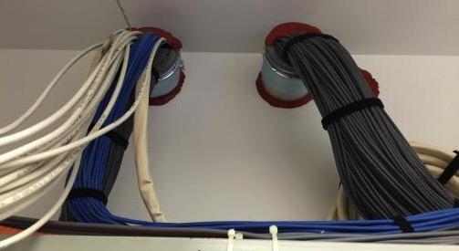
Shows Overfilled Sleeves with firestop only installed on the top side of the sleeve.


Model codes have recognized that this will occur, and have included the following code language in their texts:


NFPA 101:8.3.5.1 - “Penetrations for cables...to accommodate...communications systems shall be protected by a fire stop system or device…”


IFC 703.1 - “Openings made therein [in fire-resistance-rated construction] for the passage of pipes...wires...and holes made for any reason shall be protected with approved methods capable of resisting the passage of smoke and fire.”


As cable networks expand, often times firestop materials are removed and not replaced.  As new cable displaces the firestop system, eventually the system is rendered non-code compliant. Fire inspection personnel should be aware of these conditions and ensure that cable sleeves are properly sealed and the fire-resistance-rating of the floor or wall assembly remains intact.
Here is a checklist of items that can be used to measure the reliability of a properly sealed cable sleeve:
  • The third-party tested and listed firestop systems will specify the permissible cable load.
  • The cable load for standard cable sleeves is calculated.  The calculated cable load is the aggregate cross-sectional area of cables as a percentage of the aggregate cross-sectional area of the sleeve.  What may appear to be a 50% visual fill, might actually be half that when calculated due to interstitial space between grouped cables.
  • Sleeves with missing or partially removed firestopping need to be repaired and cable fill percentage for the listed firestop system should be verified to ensure system remains compliant.
  • Firestop systems are mostly installed symmetrically on both sides of the wall or on top side of the floor.  However, listed firestop systems will provide greater detail.
  • Firestop materials are often red, but do not necessarily have to be.  There are no code related requirements that dictate color.
  • Listed and labeled purpose-made devices with integrated firestopping systems are available to replace traditional cable sleeves or to retrofit existing sleeves.
With the myriad of items that a fire inspector is responsible for looking at, this can prove to be one of the most critical. Having a clear understanding of fire-resistance-rated construction, fire stopping materials, and listed systems and components, can provide a more clear perspective on what to look for during inspection.  
Additional Resources


NFPA 407 Aviation Fueling Checklist


NFPA 407 is the Standard for Aircraft Fuel Servicing. The standard outlines general requirements for all aviation fueling operations and four individual fuel applications.  

General requirements (Chapter 4). These apply to all fueling operations.  Outlined in this section is general safety guidelines, fueling equipment requirements and specifications, and fueling operations requirements.

Aviation fueling facilites (Chapter 5). This section addresses requirements for fuel tanks, installation plan review requirements, system components, and acceptance testing criteria.  In addition to the requirements listed in this section, fuel tanks must also be installed per the requirements of NFPA 30.

Airport fueling vehicles (Chapter 6).  Fuel vehicle manufacturer requirements are outlined in this section. Marking, vehicle operation, and general safety requirements are also stated in this section.

Rooftop heliports (Chapter 7).  With a few exceptions, this section largely refers the reader to NFPA 418, Standard for Heliports.

Self-service aircraft fueling (Chapter 8). Provides a short list of requirements for the protection of the user.  These include location of emergency fuel shut-off switches, fire protection, informational signage, access control, and fire protection.

For fire inspectors tasked with conducting periodic inspections of these facilities, the minimum requirements can be difficult to pull from the standard.  The link below will take you to an NFPA 407 inspection checklist that can be used for guidance during an inspection.


Related posts:


Information: 503-969-2028 or marc.kilman-burnham@amr.net.


How to Obtain Building Occupancy


When you start out on a building project, whether a new structure or a renovation, the ultimate goal is always the same -- building occupancy.  The goal is to occupy the structure as soon as possible, without any problems, and within (if not under) budget.   

When all the steps in a building project are carried out correctly these objectives can easily be achieved.  However, there almost inevitably, seems to be a hitch in the process.  Some part of the process that is not quite right that wants to derail the project and keep you out of the building.  These problems can arise anywhere, from the beginning in plan review and permitting, through construction and site 'surprises', to the final testing and inspections.  

With adequate resources, proper systems, and the right team in place the process can go smoothly, and be an enjoyable experience (rather than fret and stress filled).  My special white paper, The Road to C.O. - the Direct Route to Building Occupancy, reveals:

  • how to avoid the most common disapprovals in plan review
  • the importance of a properly trained and 'code knowledgeable' team
  • how to address jurisdictional issues with the local AHJ (authority having jurisdiction)
  • how to pass your final inspections with ease and peace of mind

Download the FREE guide now:


Understanding Pre-Action Sprinkler Systems

When installing a fire sprinkler system there are three general types, wet-pipe, dry-pipe, and pre-action. A wet-pipe system contains water under pressure at all times and utilized closed sprinkler heads. A dry-pipe system is used in areas where temperatures drop to less than 40 degrees Farenheit, contains no water in the above ground piping prior to system activation, and is charged with air under pressure. The pre-action system, similar to the dry-pipe, is charged with air under pressure.


In a pre-action system the water supply is held back by a pre-action valve. This valve is connected to a supplemental detection system. Water will not enter the pipe until the detection system is activated. Once activated, the valve is released and allows water into the sprinkler piping. Water will not come from the system, until sufficient heat causes the individual sprinkler head to activate (after the pre-action valve activates, the system functions the same as a wet-pipe system). This type of operation is known as a standard or single-interlock system.


The air pressure on the pre-action valve is constantly monitored. If the pressure changes (due to leak in pipe or other issue) an alarm will sound, however, the system will not activate under this condition. The valve will remain closed, preventing water running into the system until the detection system is activated.

Another type of pre-action system known as a double-interlock system will only operate when both the supplemental detection system and a sprinkler head is activated.


These systems are commonly found in high value areas such as computer rooms, communications centers, and museums.

These systems are to be installed per the requirements of NFPA 13 and NFPA 72. The following inspections are required for system acceptance:

1. Standard hydrostatic test at 200psi for 2 hours.

2. Air pressure leakage test at 40psi for 24 hours.

3. Signage and labeling of all controls and valves to be posted.

4. Alarms monitoring the supervisory air pressure shall be tested.

5. Flow switch and water flow alarm are to be tested.

6. Operational test shall be performed, requiring the pre-action valve to trip.

7. The supplemental detection system shall be tested without operating the pre-action valve.

8. Full fire alarm system function test to be conducted.